Destructive and Non-Destructive Testing and Evaluation Services

Forensic investigations and material assessments often require partial destructive testing of engineered structural elements and/or building materials. Sampling materials for laboratory studies to determine their physical properties, chemical composition, and/or behavior under a specific load condition is an essential aspect of YA’s comprehensive investigative approach.

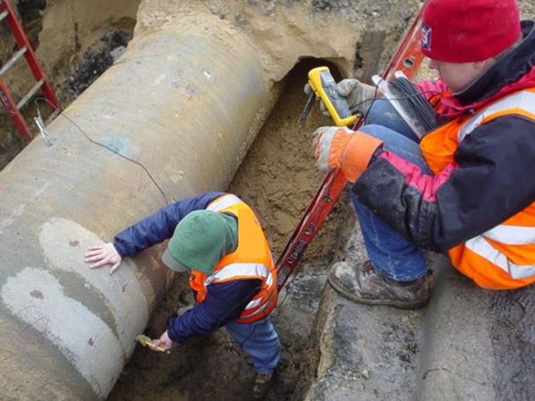
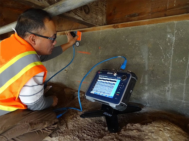
Determining the root cause of distress often involves performing partial on-site destructive testing to expose construction assemblies or extracting material specimens to examine in a laboratory setting. Other times, load testing of in-situ elements is necessary to verify as-built capacities. YA has developed professional relationships with several accredited, private, governmental, and academic testing laboratories nationwide that can facilitate standardized material testing.

YA professionals routinely perform investigations requiring on-site, partial destructive testing of materials for specific applications, including concrete, masonry, stone, wood, and steel structures, anchoring systems, roofing systems, building enclosure systems, etc.

EVALUATION METHODS:

  • Pullout testing (ASTM C900)
  • Pull-off testing (ASTM C1583)
  • Windsor probe testing (ASTM C803)
  • pH concrete determination (ASTM D4262)
  • Carbonation profiles in concrete
  • Chloride-ion penetration test (ASTM C1202, C1218)
  • Half-cell potential testing (ASTM C876)
  • Concrete compressive strength (ASTM C39)
  • Petrographic Examination of hardened concrete (ASTM C856)
  • Adhesion field test weatherproofing sealant joints (ASTM C1521)
  • Building Enclosure Testing
  • Roofing
  • Steel coupons

Ground Penetrating Radar

Ground-penetrating radar (GPR) is a non-destructive test method that involves transmitting and reflecting electromagnetic waves into a structure or material. GPR testing detects a reflected electromagnetic pulse’s arrival time and energy level. Electromagnetic energy is affected by changes in the dielectric properties of the materials, thus variations in the condition and configuration of the structure will cause changes in the received signal. Information is obtained by evaluating the return time, amplitude, shape, velocity variations, attenuation, and polarity of the signal

APPLICATIONS

GPR testing is commonly used to estimate the thickness of concrete and multi-layer systems, locate embedded reinforcement in concrete, locate wall anchors and underground utilities, measure concrete cover thickness, locate moisture variations, locate voids and identify their lateral dimensions, to locate honeycombing, cracking and delaminations in concrete, and to assess the degree of concrete deterioration due to corrosion of embedded reinforcement.

GPR is also used to investigate other construction materials, such as stone, masonry, and soils. It is very effective in determining whether CMU wall systems are grouted and the condition of the grout.

  • BENEFITS:
  • One-sided method
  • Continuous collection of data
  • System portability
  • 3D views of processed data
  • No risk of harmful radiation
  • Data can be collected with vehicle-mounted antennae or drones.

Half-Cell Potential Corrosion Survey

Half-cell potential (HCP) is a nondestructive test method used to investigate the thermodynamic corrosion tendency of embedded reinforcing steel. Potential readings measure the electrical activity of the corrosion process. Corrosion occurs simultaneously at steel’s anode and cathode areas when iron ions are released (at the anode areas) into the concrete to react and form deposits (at the cathode areas).

The HCP method involves making one electrical connection between reinforcing steel and the positive terminal of a high-impedance voltmeter and another between the negative terminal of the voltmeter and a reference electrode (RE). The RE comprises a copper electrode enclosed in a plastic housing surrounded by a saturated copper sulfate solution. The end of the cell is a porous disk through which the copper sulfate solution can make electrical contact with the concrete. The copper-copper sulfate (CSE) reference cell is the most widely used half-cell RE.

YA professionals have vast laboratory and field experience investigating corrosion-related problems in concrete structures related to the penetration of chlorides and/or carbonation of concrete. Carbonation occurs when CO2. from the atmosphere reacts with concrete. The HCP test method follows the procedures recommended by ASTM C876, Standard Test Method for Corrosion Potentials.

APPLICATIONS

The HCP test method is used to identify the probability of corrosion activity of steel reinforcement in reinforced concrete structures. YA professionals have extensively used it to investigate corrosion activity in reinforced concrete bridge decks, tunnel liners, plate-like structures such as walls and slabs, and structures such as beams and columns.

BENEFITS

  • Economical
  • Repeatable measurements
  • Used for predictive maintenance
  • Allows for assessment of large areas
  • Commonly used to correlate results with other NDT methods

Impact-Echo (IE)

Impact-echo (IE) is an ultrasonic testing technique that entails introducing mechanical energy, in the form of a short pulse, into a structure and measuring its response. A transducer mounted on the impacted surface of the structure receives the reflected input waves or echoes as changes in the acoustic impedance in the materials are detected. Spectral analysis of the reflected compression wave is then performed to identify flaws and/or deterioration in the concrete or other material and to measure the thickness.

YA engineers have extensive experience using the IE test method. In the 1990s, they collaborated with the Federal Highway Administration (FHWA) Turner-Fairbank Highway Research Center in McLean, VA, in researching and developing the technology. YA has applied the IE test method to identify concrete-related problems in bridges, tunnels, slabs, foundations, pavements, masonry, and stone facades.

APPLICATIONS

The IE test method is commonly used in concrete, stone, shotcrete, and masonry structures to detect internal flaws such as honeycombing, voids, and delaminations. It is also used to detect freezing and thawing deterioration, grout conditions in post-tensioned tendon ducts, and grout conditions in CMU construction. It is also an effective tool to assess the overall quality of concrete.

BENEFITS

  • One-sided test method
  • Estimates concrete thickness without coring
  • System portability
  • Reliable and repeatable results when performed by experienced operators

Shear Wave Ultrasonics

The Ultrasonic Shear Wave Tomography (USWT) test method, commercially known as the MIRA test unit, is a flaw detection system capable of generating 2D and 3D tomographic images of structural elements. The basic system consists of a console with 48 transducers aligned in 12 rows of modules containing four shear wave transducers each. The transducers are spring-loaded, dry-point contact (DPC) piezoelectric sensors with a center frequency of 50 kHz, configured as a single antenna array. Each transducer is built with a wear-resistant ceramic tip, which allows testing on rough surfaces without coupling gels.

Once the ultrasonic shear wave signal is emitted, the received signal is processed by the controlling console, and the 2D b-scan image is immediately displayed on the built-in screen. Then, a modified synthetic aperture focusing technique (SAFT-C) data processing analysis method is performed to generate 3D images of the test results.

YA engineers have extensive experience using the USWT test method to investigate a variety of concrete-related issues. Our engineers participated in the original research and development of the technology with the equipment manufacturer in the late 1990s.

APPLICATIONS

The USWT test method is commonly used in concrete, stone, and masonry structures to detect internal flaws such as delaminations, cracks, and poorly consolidated or honeycombed concrete and to locate voids in grouted tendon ducts. One key application of the MIRA system is the ability to assess thick concrete structures such as nuclear power containment walls or subterraneous subway shafts. YA engineers have used the USWT test method to investigate concrete structures up to 2 meters thick.

BENEFITS

  • One-sided method
  • Generates 2D and 3D images of test results
  • System portability
  • Works on rough concrete surfaces
  • Effective for testing thick concrete structures

Ultrasonic Pulse Velocity

Ultrasonic Pulse Velocity (UPV) is an ultrasonic testing technique that measures and assesses the transit time of reflected pulse stress waves through a material.

Detected changes in arrival time, amplitude, and the characteristics of the propagated mechanical waves can indicate changes in the internal makeup of the material. In concrete, internal conditions, such as the presence of honeycombing, internal cracking, and paste voids, affect the ability of a pulsed ultrasonic wave to propagate. While anomalies may slightly affect the transit time, and thus the corresponding computed pulse velocity, the effect on the signal strength and wave characteristics is more significant. Transient waves moving through anomalies will be attenuated, resulting in less total signal energy received through the member thickness.

APPLICATIONS

The UPV test method is commonly used to detect internal flaws such as honeycombing, voids, and delaminations in concrete, stone, shotcrete, and masonry structures. UPV testing is also widely used to determine the overall quality of concrete and cementitious materials based on analysis of the compressional waves’ signal characterization and propagation velocities.

YA professionals have extensive experience using the UPV test method and have conducted all manner of investigations to solve construction-related problems involving conventionally reinforced concrete, prestressed and post-tensioned concrete structures, wood structures, and many other applications related to plastic and composite materials.

BENEFITS

  • System portability
  • Instantaneous results
  • Reliable and repeatable results when performed by experienced operators.
  • Often used as a material quality control test method.

Infrared Survey

Infrared Thermography (IR) is a nondestructive test method that utilizes an infrared camera to produce visual images that display materials’ thermal signatures. IR cameras use a germanium lens to detect invisible infrared radiation of a material and convert the corresponding intensity into a two-dimensional image representing temperature differentials. Temperatures are shown onscreen as shades and/or colors representing the emitted, transmitted, or reflected energy detected by the camera.

IR energy operates in the invisible portion of the electromagnetic spectrum extending from 0.75 to 1000 microns (µm). All objects warmer than absolute zero (0° K or -275.15°C) emit energy somewhere within that range. IR can instantly detect subsurface anomalies within and below the test elements.

APPLICATIONS

IR can detect anomalies in surface radiance that may be related to a subsurface condition of the material. IR is commonly used to detect internal flaws such as delaminations, cracks, and poor consolidation or honeycombing in concrete, stone, and masonry structures. IR can detect problems related to moisture intrusion, air exfiltration, heat loss, or material defects for building envelope applications. Interpretation of IR images requires careful attention by a trained IR thermographer. YA engineers and architects have extensive experience using IR to investigate building performance issues, including moisture surveys for roof and cladding assemblies, air leakage testing, determining the presence of grouted cells in CMU construction, locating defects within layers of fiber-reinforced polymer sheets, and numerous other applications.

BENEFITS

  • Completely non-invasive and nondestructive test method
  • Provides estimates of the size of the deteriorated area
  • Used as predictive maintenance
  • Allows for large areas to be assessed